What is Amroba?
Amroba is a browser-based digital design and simulation platform for designing and simulating digital circuits. It enables complex circuits to be decomposed into smaller, reusable building blocks. Using Amroba, systems can be designed from simple logic up to full computer architectures.
Amroba in a glance
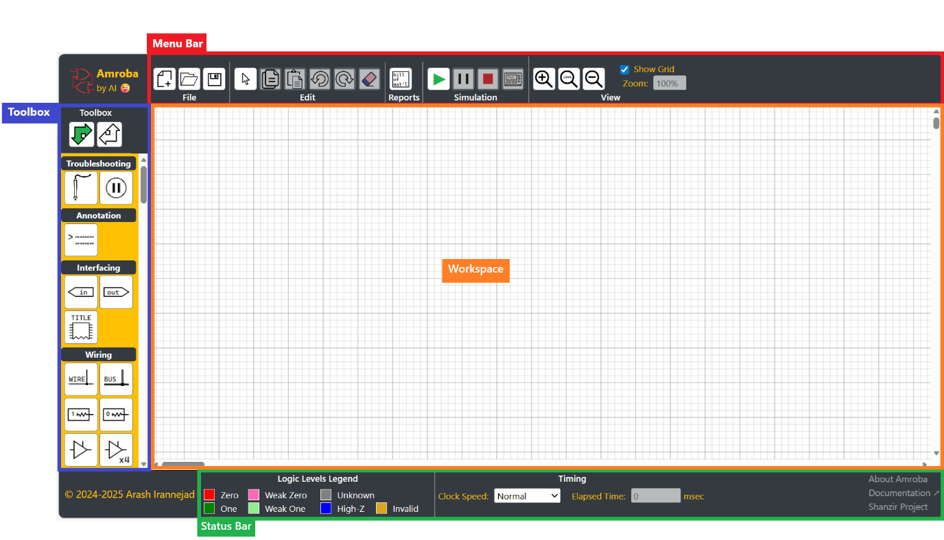
The Amroba interface is structured into four primary sections:
Menu Bar: providing access to design management and system commands
Toolbox: containing wiring tools, logic elements, components, and user-defined sub-circuits
Workspace: serving as the main environment where circuits are created and edited
Status Bar: displaying system status, simulation controls, and operational feedback
Menu Bar in a glance
The Menu Bar includes the following functional groups:
File: contains commands for managing circuit files
 New circuit. The current circuit in the Workspace will be wiped out.
 Opens a previously saved circuit from the local machine.
 Saves the current circuit to the local machine.
Edit: provides commands to modify the current circuit within the Workspace. See also Workspace in a glance
 Resets to Edit mode. It clears the selection.
 Copies the selection to the application clipboard.
 Pastes the application clipboard into the Workspace
 Reverts the most recent action
 Restores the last undone action
 Deletes the selection from the current circuit in the Workspace
Reports: provides analytical information about the current circuit
 Lists all the components in the current circuit including all its sub-circuits. See also Bill of Material in a glance
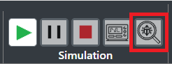
Simulation: provides controls to evaluate the circuit by computing all signal states based on inputs. See also Simulation in a glance
 Starts the simulation
 Pauses the simulation
 Stops the simulation and returns to Edit mode
 Opens the Recorder window. See also Probes and Recorder in a glance
View: includes the commands to modify the presentation of the Workspace
 Zooms into the current circuit progressively up to a factor of 300%
 Resets the zoom factor to 100%
 Zooms out of the current circuit progressively down to a factor of 25%
Show Grid enables and disables grid in the Workspace
Zoom displays the current zoom level
Toolbox in a glance
The Toolbox provides components and tools used to construct circuits within the Workspace.
Depending on the direction of information in each segment of the circuit, the orientation of components can be configured as follows:
 left-to-right / top-to-bottom, or
 right-to-left / bottom-to-top
Tools are categorized into various groups:
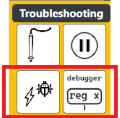
Troubleshooting: provides tools for debugging and signal inspection
 probes into any wire or bus. The trend of detected signal will be shown on Recorder. See also Probes and Recorder in a glance
 automatically pauses simulation where a signal value becomes 1. See also Simulation in a glance
Annotation: provides tools to attach extra information to a circuit
 adds textual annotations
Interfacing: provides tools to create sub-circuits. See also Sub-circuits in a glance
 acts as an input to a sub-circuit
 acts as an output from a sub-circuit
 defines title of a sub-circuit
Wiring: provides tools to link components to each other. See also Wires in a glance and Buses in a glance
 enables propagation of logic states from an output of a component to input of a component.
 enables shared reading and writing of logic states by components on a common bus.
 are soft 1 and soft 0 generators, respectively
 are tri-state bus buffers.
Terminals: provides tools to link wires and buses.


 are unidirectional feed-through terminal strips for wires


 are bidirectional feed-through terminal strips for buses
Inputs: provides input sources for wires. See also Logic Levels in a glance

 are static hard 1 and static hard 0 generators, respectively
 are momentary switches with normally hard 1 and hard 0 values, respectively
 are maintained switches with initial hard 1 and hard 0 values, respectively
 is the clock generator
Output: provides tools to monitor logic values of wires and buses. See also Logic Levels in a glance
 displays logic value of a single wire or bus
 display numeric values in 8-bit and 16-bit formats, respectively
Gates: provides logic gates.

 are AND gates in different quantities
 are OR gates in different quantities
 are XOR gates in different quantities
 are INVERTER gates in different quantities
 are NAND gates in different quantities
 are NOR gates in different quantities
 are XNOR gates in different quantities
Multiplexers: provides multiplexers / encoders.


 are n-to-1 multiplexers in different quantities
 is a priority line encoder
Demultiplexers: provides demultiplexers / decoders.

 are 1-to-n demultiplexers
Flip-Flops: provides flip-flops.


 are D type flip-flops in different quantities
 is a J-K type flip-flop
Counters: provides counters.
 is a binary counter
Memory: provides persistent and temporary memories.

 are RAMs (Random Access Memories) in different capacities.
 is a ROM (Read Only Memory)
 is a DP-RAM (Dual-Port Random Access Memory)
Arithmetic: provides arithmetic functions.
 is a full adder
 is a magnitude comparator
Sub-circuits: provides tools to manage user-defined sub-circuits. See also Sub-circuits in a glance
 loads a sub-circuit into toolbox
 selects a sub-circuit
 removes a loaded sub-circuit from toolbox
Chip equivalence table
Table below lists components available in the toolbox with their commercially available 74HC series equivalent.
| Group | Component | Equivalent chip | Quantity per chip | Sample Datasheet |
|---|---|---|---|---|
| Wiring | Bus Driver | 74HC126 | 4 | Link ↗ |
| 74HC541 | 8 | Link ↗ | ||
| 74HC365 | 6 | Link ↗ | ||
| 74HC244 | 8 | Link ↗ | ||
| Gates | AND gate | 74HC08 | 4 | Link ↗ |
| OR gate | 74HC32 | 4 | Link ↗ | |
| XOR gate | 74HC86 | 4 | Link ↗ | |
| INVERTER gate | 74HC04 | 6 | Link ↗ | |
| NAND gate | 74HC00 | 4 | Link ↗ | |
| NOR gate | 74HC02 | 4 | Link ↗ | |
| XNOR gate | 74HC266 | 4 | Link ↗ | |
| Multiplexers | Quad 2:1 Multiplexer | 74HC157 | 1 | Link ↗ |
| 4:1 Multiplexer | 74HC153 | 2 | Link ↗ | |
| 8:1 Multiplexer | 74HC151 | 1 | Link ↗ | |
| 8:3 Priority encoder | 74HC148 | 1 | Link ↗ | |
| Demultiplexers | 2:4 Demultiplexer | 74HC139 | 2 | Link ↗ |
| 3:8 Demultiplexer | 74HC138 | 1 | Link ↗ | |
| 74HC137 | 1 | Link ↗ | ||
| Flip-Flops | D flip-flop | 74HC175 | 4 | Link ↗ |
| 74HC74 | 2 | Link ↗ | ||
| 74HC174 | 6 | Link ↗ | ||
| 74HC273 | 8 | Link ↗ | ||
| J-K flip-flop | 74HC109 | 2 | Link ↗ | |
| Counters | 4-bit counter | 74HC161 | 1 | Link ↗ |
| Memories | 8kB ROM | AT28C256 | - | Link ↗ |
| 8kB RAM | CY7C185 | - | Link ↗ | |
| 32kB RAM | CXK58257 | - | Link ↗ | |
| 4kB Dual port RAM | IDT7134 | - | Link ↗ | |
| Arithmetic | 4-bit full adder | 74HC283 | 1 | Link ↗ |
| 4-bit comparator | 74HC85 | 1 | Link ↗ |
Workspace in a glance
You can create and modify circuits in the Workspace by:
Adding components in the Workspace
Select a component from group the toolbox by left click on mouse.
Move mouse to the Workspace to the desired location. A copy of the selected component will move along the mouse pointer.
Add the selected component to the Workspace by left click on mouse.
Notes:
A selected component cannot be placed on top of any part of the circuit in the Workspace
A selected component can be placed right next to the existing wiring if the result is valid. In this case the linking will automatically happen. See also Valid wiring rules.
Drawing wires in the Workspace
Select wire from group the toolbox by left click on mouse.
Start the wire by moving mouse to the Workspace to the desired location. It could be:
Somewhere empty to start a new wire
On an existing wire to start an extension to that wire
To a pin on an existing component – either an input pin or an output pin
Continue the wire by left click in the Workspace in vertical or horizontal direction in any number of times
Finish the wire by:
Either right click in the Workspace or pressing the ESC key, or
Connecting to an existing component.
Notes:
A wire can have only one input (i.e. output pin of a component). However, it can be connected to input pin of multiple components.
For practical reasons, a wire linking two output pins is not allowed.
Drawing buses in the Workspace
Select bus from group the toolbox by left click on mouse.
Start the bus by moving mouse to the Workspace to the desired location. It could be:
Somewhere empty to start a new bus
On an existing bus to start an extension to that bus
Continue the wire by left click in the Workspace in vertical or horizontal direction in any number of times
Finish the bus by right click in the Workspace or pressing the ESC key
Notes:
A bus can have multiple inputs (i.e. 3-state output pin of a component). However, it can be connected to input pin of multiple components through its extensions
Selecting a part of circuit
Press and hold the left button of mouse at one of the corners of the imaginary rectangle covering the intended selection
Move your mouse the opposite corner of selection and release the left button. The colour of selected components will become red.
Copy and pasting a selection
Select part of a circuit
- Press Ctrl+C or click on to copy the selection to the application clipboard
- Press Ctrl+V or click on to display the application clipboard. Click on an admissible place in the Workspace to insert the pasted circuit.
Notes:
For valid insertions the circuit from the clipboard is displayed in green. For invalid insertions it is displayed in red.
You cannot place a copied sub-circuit touching any part of the circuit already in the Workspace.
Selecting segments of a wire with extensions
Select a wire. The entire wire will be highlighted in red
Click on an extension on the wire (which has no extension on it). Only the clicked extension will be selected, and the rest of wire will be unselected.
Note:
Only deletion of wire extension is supported.
Undoing an action
- Press Ctrl+Z or click on to undo the last action.
Repeat as many times as needed
Note:
Starting a new design will reset the previous actions buffer.
Redoing an undone action
- Press Ctrl+Y or click on to undo the last action.
Repeat as many times as needed
Note:
Redoing an action only can happen after an undo operation
Deleting a selection
Select part of a circuit
- Press Delete or click on to delete the selection
Bill of Material in a glance
To get a list of components used in the current circuit in the Workspace (including all sub-circuits), click on . A new window will open which displays each component type, equivalent ICs (along with number of pins for each IC), and quantity of the components in the current design.
Simulation in a glance
You can enter simulation mode by clicking on during which input components will become active and provide inputs to the circuit in the Workspace. In this case:
- Static inputs and will provide a constant value of 0 and 1 correspondingly to the wire on their output,
- Static inputs and (with pullup and pulldown resistors) will provide a constant value of 0 and 1 correspondingly to the bus on their output only if there is no value already on that bus.
- Maintained switches and will provide an initial constant value of 0 and 1 correspondingly to the wire on their output, however the value will toggle (and retained) by clicking on each input on the circuit.
- Momentary switches and will provide an initial constant value of 0 and 1 correspondingly, however the value will toggle (and retained) by pressing on each input on the circuit. The value returns to its initial state when the press is released.
- Clocks will generate an alternating signal of 0 and 1.
Note: when simulation is running, you cannot edit the circuit.
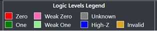
Logic Levels in a glance
In the simulation mode, each wire and bus will be coloured to represent their logical value listed in the table below.
| Color | Logic Value | Applicable to | Meaning |
|---|---|---|---|
| Red | Hard Zero | Wire and Bus | There is only one input to the wire or bus and its value is Zero |
| Green | Hard One | Wire and Bus | There is only one input to the wire or bus and its value is One |
| Light Red | Weak Zero | Bus | There is no input to the bus, however bus is connected to a source with value of Zero through a resistor. |
| Light Green | Weak One | Bus | There is no input to the bus, however bus is connected to a source with value of One through a resistor. |
| Grey | Unknown | Wire and Bus | No input available to the wire or bus |
| Blue | High-Z | Bus | All inputs to the bus are in High-Z state |
| Amber | Invalid | Wire and Bus | Multiple inputs to the bus are not in High-Z state, or Output of a component connected to a wire or bus is not well-defined for its inputs` |
For quick reference, the legend below has been added to the Status Bar
By clicking on , the simulation will be paused, and the following message will appear in the Status Bar:
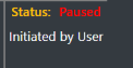
In this case the inputs will be kept unchanged until the is clicked again. This is useful when you are using clocks and you need time to analyse the states of the circuit before the clock values toggles.
By clicking on , the simulation will be ended, and circuit can be edited again.
By clicking on , a scope will appear and shows values of all wires and buses which have probes associated to. See also Probes and Recorder in a glance.
Notes:
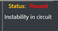
Amroba evaluates the entire circuit simultaneously (i.e. no sequential execution order is imposed on components). If the circuit fails to reach a stable state, simulation will be paused and the following message will appear in the Status Bar:
Timing section in the Status Bar – as shown below – allows you to select how fast or slow the simulation should run.
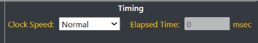
Clock Speed dropdown will provide you these options (in order of speed):
Quiet - 10 times faster than Normal. Logic value colours will not be applied to wires and buses.
Fast – 10 times faster than Normal. Logic value colours will be applied to wires and buses.
Normal – Nominally 1 pulse per second
Slow – 10 times slower than Normal
Stopped – Clocks will not generate any pulse
Elapsed Time box will show you how much time has passed since start of the simulation.
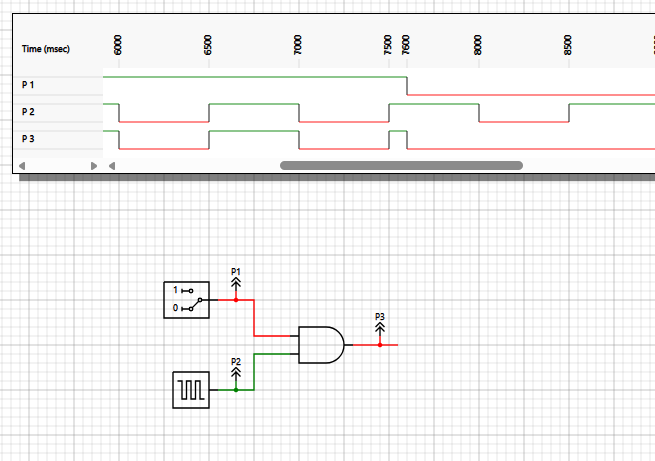
Probes and Recorder in a glance
To have the trend of values of different parts of a circuit in one place, using add probes to desired wires and buses. By opening the Scope by clicking on during the simulation, values corresponding to each probe are shown synchronously. Changes to state of any part of the circuit will trigger Scope to show values.
In the example below, the input switch has manually changed by the user from value 1 to value 0 at 7600 msec.
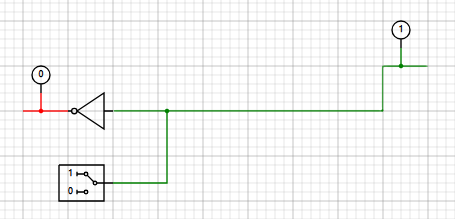
Wires in a glance
Wires are used to propagate signals from the output of a component to input pins of one or more components.
Wires can be started from either input pin of a component, output pin of a component, any points inside an existing wire or even not connected to any component. When drawing a wire is started, you can continue vertically or horizontally in the Workspace by clicking left click. Wires will be finished if either you connected it to a valid pin on a component, right click in the Workspace, or press ESC key.
In the example below, a wire (with one branch) is shown which has one input and outputs to two components.
Buses in a glance
Buses are used to distribute signals from multiple components to input pins of one or more components. Since only one active driving signal is permitted on a bus at any given time, only components supporting a high-Z output can be connected to the bus.
To draw a bus in the Workspace, be mindful that both sides of a bus shall be left unconnected to anything. When drawing a bus is started, you can continue vertically or horizontally in the Workspace by clicking left click. buses will be finished if either you right click in the Workspace or press ESC key.
To connect a bus to any component, start drawing a branch from a point on an existing bus and finish it to input or output pin of a component.
In the example below, a wire (with one branch) is shown which has one input and outputs to two components.
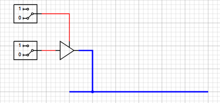
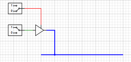
In both the examples below, the bus buffer output is not enabled. Regardless of the value of the buffer input, the bus will remain in high-Z state.
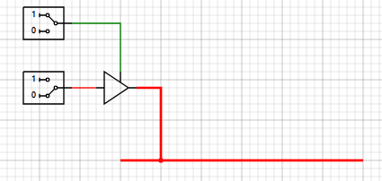
In both the examples below, the bus buffer output is enabled. The bus will follow the value of the buffer input.

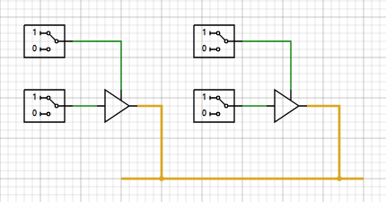
In the example below, the bus buffer outputs of both buffers are enabled. Regardless of the value of the buffers input, the bus will remain in Invalid state.
Constant inputs with pull-down/pull-up resistors can be used to set value of a bus to a default value in case no input is active to avoid having a high-Z state on the bus.
In the example below, the bus buffer output is not enabled and the value the bus will be the value of the constant input 1.
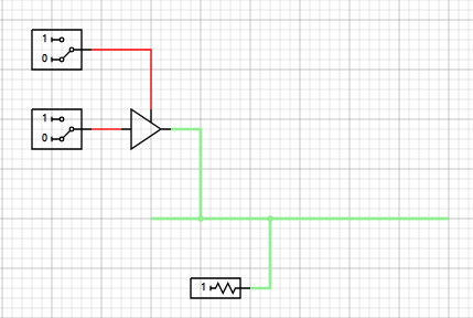
Note that the default values of the bus have a higher colour: light red for a soft zero and light green for a soft one.
Sub-circuits in a glance
A circuit with defined inputs and outputs can be saved on local computer to be re-used inside another circuit as a sub-circuit to promote reusability, modularity and cleaner design.
To create a subcircuit, add inputs and outputs to intended place into your designed circuit. Click on any input pin or output pin to pin name, order and location of the pin using the Component Properties tab in the Menu Bar:
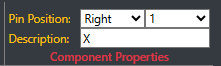
Place a title in the Workspace to assign a descriptive name to the subcircuit. Click on the title to update the description using the Component Properties tab in the Menu Bar. Save your circuit on the local computer for future use.

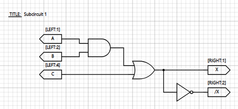
Example below shows a circuit with 3 inputs and 2 outputs named “Subcircuit 1”.
A subcircuit should be added to the Toolbox before it can be inserted in another circuit. To use a subcircuit in a circuit. Find any unused slot in the “sub-circuit section”:

An existing subcircuit can be assigned to that by clicking on its open icon  and adding the file path:
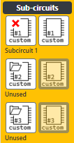
An added subcircuit can be selected from the toolbox by clicking on its icon  and inserted by clicking at valid point in the Workspace.
An added subcircuit can be removed from the toolbox by clicking on its deletion icon and subsequently, its slot becomes available.
Shanzir Project and Shanzir Mode
Shanzir Project is an attempt to develop and test a working computer using Amroba and eventually built it using commonly available components. For more information, click on the link shown below in the Status Bar.

When the About Shanzir is open, you can enable or disable Shanzir mode.

In Shanzir mode, two extra tools in Toolbox and one extra function in the Menu Bar are available to work specifically with the circuit developed for Shanzir Project.
For full technical details, schematics, and development notes, visit www.shanzir.com.